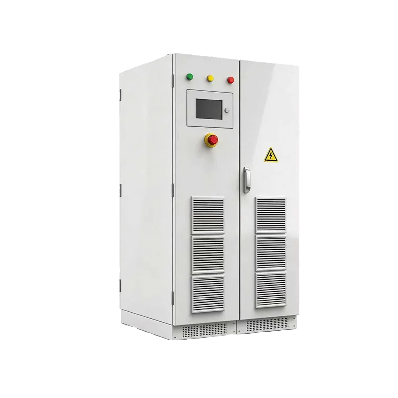
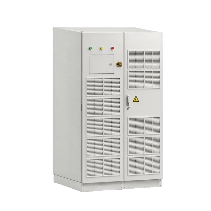
LEONA-B750K 750 kW Split-Type Hybrid Inverter System
At a glance
LEONA-B750K is VGRID’s 750 kW split-type hybrid inverter and energy-storage conversion system. It combines a grid-forming PCS, EMS, isolation transformer and grid/off-grid switching in an IP54 cabinet. PV MPPT controllers are separate optional units; the design supports six battery branches, six PV/MPPT interfaces, utility or generator input, and DC- or AC-coupled microgrid solutions.
Key Features
- 750 kW class split-type hybrid inverter / energy-storage conversion system; brochure AC output: 750 kVA rated, 825 kVA maximum
- Grid-forming PCS with PQ, VF, droop and VSG operating modes
- IP54 cabinet, built-in isolation transformer, EMS and automatic grid/off-grid transfer under 20 ms per brochure
- Six battery connection branches and six PV/MPPT output interfaces; PV MPPT controllers are separately selected
- Direct PV wiring interface is designed to avoid a separate combiner box in the documented configuration
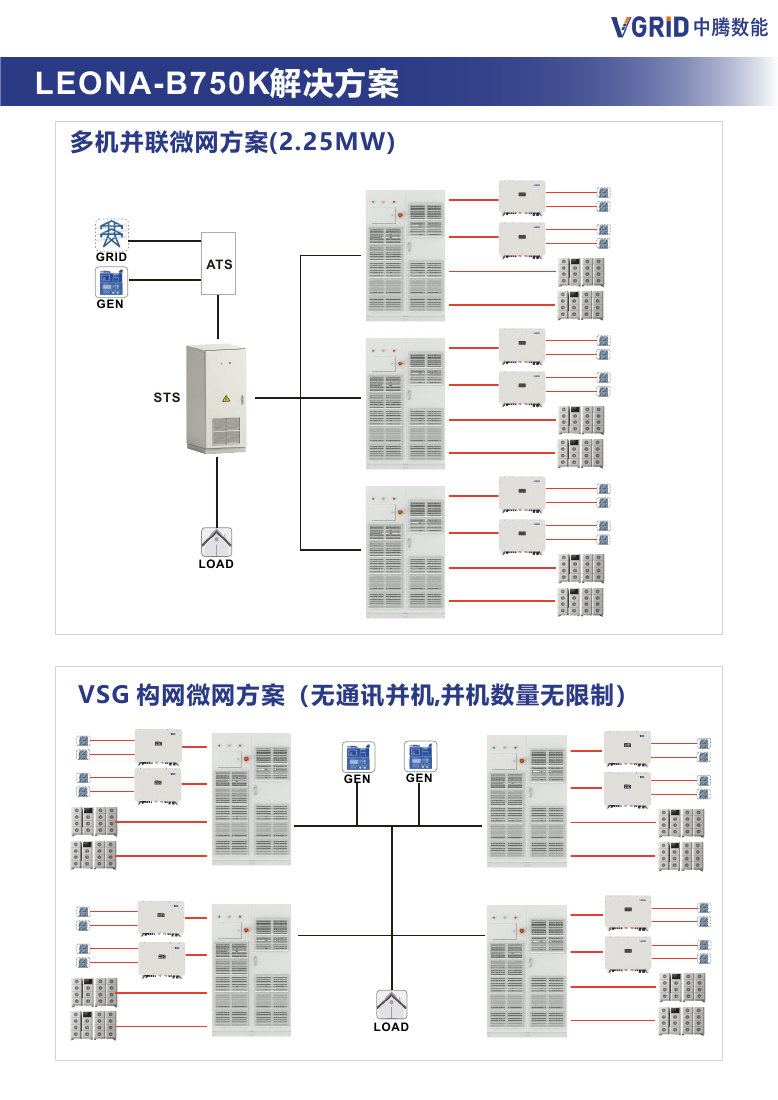
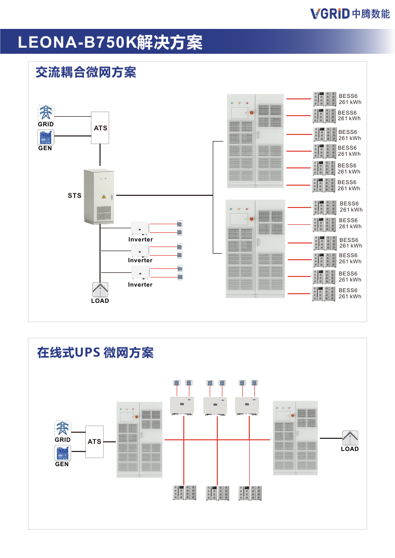
- Brochure includes DC-coupled, 2.25 MW parallel, VSG parallel, AC-coupled and online UPS solution diagrams
Product Description
LEONA-B750K: a split-type hybrid inverter system for microgrids
The new product name in the latest brochure is LEONA-B750K. It is a split-type energy-storage conversion system for commercial and industrial microgrids. The user-confirmed product class is 750 kW. The brochure’s electrical table separately lists 750 kVA rated off-grid apparent output, 825 kVA maximum output and 1194 A maximum output current; confirm the active-power nameplate and final configuration on the project datasheet.
Architecture and core equipment
The cabinet combines a grid-forming PCS, EMS, isolation transformer and automatic grid/off-grid switching. The enclosure is IP54. The architecture keeps PV MPPT controller units separate, so they can be selected and located near the PV array. The brochure shows six battery branches (BAT1–BAT6) and six PV/MPPT interface groups. PV direct-wiring interfaces are intended to avoid a separate combiner box in the documented arrangement; confirm string fusing and protection against the final single-line diagram.
Power path: PV strings → separately selected MPPT controller(s) → LEONA-B750K DC interface ↔ battery branches; PCS ↔ isolation transformer ↔ AC load bus. Utility and generator inputs connect through the system transfer arrangement shown in the project diagrams. AC-coupled PV inverters and DC charging equipment can be included when the interface and control design are approved.
Operating modes and control
The brochure lists PQ, VF, droop and VSG grid-forming modes. It describes active state-of-charge balancing for parallel battery clusters, boost-buck conversion so PV output voltage is not constrained by battery voltage, PV reverse-polarity protection, short-circuit protection, cloud diagnostics, event and waveform records, and remote OTA updates. The brochure states automatic grid/off-grid transfer under 20 ms; verify the test conditions and transfer device in the offered configuration. PV-side ground-fault behavior should be confirmed against the manufacturer’s detailed protection document for the project.
Published electrical and environmental data
- Battery: 680–900 V rated range, 950 V maximum; up to 200 A × 6 branches as listed.
- AC off-grid output: 750 kVA rated, 825 kVA maximum, up to 1194 A; rated voltage 400/230 V.
- Grid range: −20% to +15%; 50 Hz (47–52 Hz) or 60 Hz (57–62 Hz).
- Overload: 1.1× continuous, 1.25× for 60 s, 1.5× for 100 ms below 35 °C.
- Maximum efficiency 97.8%; built-in Znyn0 isolation transformer; IP54.
- Dimensions 1200 × 2018 × 1227 mm; approximately 2700 kg; −30 to 60 °C with derating above 45 °C.
Solutions shown in the LEONA-B750K brochure
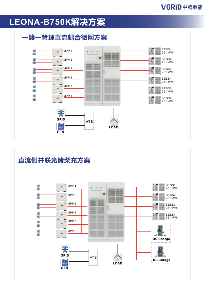
DC-coupled microgrid, one cluster per controller: PV arrays connect to separate MPPT units; six battery clusters are shown at 261 kWh each, while grid and generator feed the source-transfer arrangement. DC-coupled storage and charging: the diagram shows four 261 kWh battery clusters and DC chargers on the DC bus. 2.25 MW parallel microgrid: the brochure presents three 750 kW-class cabinets in a parallel system with grid, generator, ATS and STS. VSG parallel: a communication-free parallel arrangement is illustrated; the claimed “unlimited” unit count requires written engineering validation. AC-coupled and online UPS: existing PV inverters and critical loads connect through the illustrated transfer and storage architecture. Battery energy values and one-line topology in these diagrams are examples, not a project design guarantee.
Ports and installation interfaces
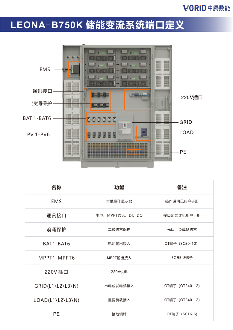
Cabinet ports include BAT1–BAT6 battery outputs, PV1–PV6 / MPPT interfaces, GRID three-phase four-wire input, LOAD three-phase four-wire output, PE grounding bar, EMS/communications and a 220 V service outlet. The brochure identifies OT terminals for battery, grid and load and separate SC terminals for MPPT output; use the cabinet terminal drawing and supplied manual for conductor selection. ATS/STS and upstream protective-device requirements are defined at system level.
Downloads and engineering boundary
Download the latest LEONA-B750K brochure and request the configuration-specific single-line diagram, parallel control statement, transfer test conditions, battery interface requirements and applicable certificates. Confirm battery cluster limits, controller count, PV protection, generator synchronization, ATS/STS ratings, grounding, fault levels and applicable grid rules before final design.
Compare the SP375HAG2 / SP500HAG2 hybrid cabinets when integrated MPPT is preferred, or the LEONA-M200K wall-mounted MPPT controller for a separately deployed PV conversion stage.
Specifications
| Model | LEONA-B750K |
|---|---|
| Rated active power | 750 kW class (project-confirmed); verify against nameplate |
| AC off-grid rated apparent output | 750 kVA |
| Maximum AC output apparent power | 825 kVA |
| Maximum AC output current | 1194 A |
| Battery rated voltage range | 680–900 V |
| Maximum battery voltage | 950 V |
| Maximum battery current | 200 A × 6 branches |
| AC rated voltage | 400/230 V |
| Grid voltage range | −20% to +15% |
| Grid frequency | 50 Hz (47–52 Hz) / 60 Hz (57–62 Hz) |
| Output transfer time | <20 ms, as stated in brochure |
| Overload | 1.1× continuous / 1.25× 60 s / 1.5× 100 ms (<35 °C) |
| Maximum efficiency | 97.8% |
| Isolation transformer | Built in; Znyn0 |
| Protection / enclosure | IP54 |
| Dimensions / weight | 1200 × 2018 × 1227 mm / approx. 2700 kg |
| Operating temperature | −30 to 60 °C; derating above 45 °C |
| Humidity / altitude | 5–95% / up to 4000 m; derating above 2000 m |
Product FAQ
What is the new product name for the 750 kW cabinet?
The latest brochure identifies it as the LEONA-B750K split-type hybrid inverter / energy-storage conversion system. The existing product URL is retained to avoid breaking prior links.
Does LEONA-B750K include PV MPPT controllers?
The design uses separate MPPT controller units that can be selected and expanded as needed. The cabinet provides six PV/MPPT interface groups; confirm controller count and array allocation in the project diagram.
What are the documented AC output ratings?
The brochure lists 750 kVA rated off-grid output, 825 kVA maximum output and 1194 A maximum output current. The 750 kW class active-power designation should be checked against the final nameplate and project datasheet before procurement.
Which system configurations are shown?
The brochure illustrates one-cluster-one-management DC coupling, DC-coupled PV-storage charging, a 2.25 MW parallel microgrid, VSG no-communication parallel operation, AC coupling and an online UPS microgrid.
Does the brochure claim unlimited VSG parallel operation?
It labels the no-communication VSG configuration as having no stated unit limit. Treat this as a brochure-level control claim, not a project capacity guarantee; obtain written approval for the selected cabinet count, protection and operating conditions.
Downloads
Not sure this is the right specification?
Send us your drawing, data sheet or sample and our engineers will confirm the match within 48 hours.